Most of today’s electronic manufacturing is done in Surface Mount Technology (SMT), developed in the 1960s. It was formerly done in Through-Hole Technology (THT), which is now considered a secondary operation by assembly houses.
The 7330 main board contains 710 components, the majority of which are SMT. What’s involved in SMT manufacturing? It starts with the board.
Before the 7330, S-COM boards were manufactured with a Hot Air Solder Leveling (HASL) finish. The boards were submersed in tin/lead solder to cover all of the copper, then air knives blew hot air over the surface to level the solder and remove the excess. The resulting tin/lead layer was flat enough for THT, but not SMT.
The 7330 main board has an Electroless Nickel Immersion Gold (ENIG) finish. The copper is first coated with nickel, then with a thin layer of gold for oxidation resistance. The board looks like it’s gold plated – because it is!
Assembling the board involves several steps. Solder paste is applied using a stencil in an automated process; SMT parts are then placed by a high-speed pick-and-place machine.
The boards go through a reflow oven that has designated heat zones to allow for proper curing and cool-down of the components.
Since the 7330 also has some through-hole parts, the boards go to the through-hole department for additional assembly. Parts are loaded and mounting holes are masked. The boards are then run through a wave solder machine.
There are more than 2,100 solder connections on the 7330 main board, but there are nearly zero manufacturing defects due to the very high consistency gained with automated assembly.
Besides the low defect rate, there are other reasons for using SMT. One is that some key parts are only available in SMT, such as the 210-pin Field Programmable Gate Array (FPGA) IC.
Another reason is the small size of SMT components – they’re less expensive than THT and can be packed more densely. (The smallest parts in the 7330 are resistors and capacitors in 0603 size, or 0.06” by 0.03”.)
With THT, plated-through holes accept component leads and connect circuits on different board layers. With SMT, connections are done with much smaller plated-through holes called vias.
Shrinking the circuitry means more features can be packed into a given product size (in this case, a 1U cabinet). And shorter PCB traces mean smaller “antennas” to transmit and receive digitally-generated RFI.
Although we didn’t mount parts on both sides of the 7330 main board, it could have been done to further increase density.
Why didn’t we build the 7330 exclusively with SMT parts? User convenience and mechanical stress.
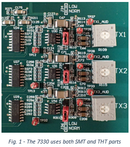 Most SMT components are secured by solder on the surface of the board and can be dislodged if physically overstressed. On the other hand, THT component leads go into plated-through holes and are soldered in place, so those components can better withstand pushing and pulling. For that reason, we use THT components where adjustments, measurements, and replacements are expected: connectors, pots, shunts, test points, and IC sockets. See figure 1.
Designing with SMT means adding features that assist customers. For example, it can be difficult to probe a tiny part without shorting adjacent connections, so we added red-colored test points for measuring important signals.
Also, since it’s inconvenient to solder and de-solder small resistors and capacitors, we added push-on shunts (jumpers) that not only set the audio gain range but also enable and disable de-emphasis, audio delay, pullup resistors, and logic inversion for COR, CTCSS, and PTT.
As an aside, you’re probably familiar with through-hole boards and have the necessary tools and a soldering pencil. But if you’ll be doing more than a little SMT work, you’ll want the right equipment. Good SMT tools are not cheap and represent an investment that pays off in the form of good service for many years.
You’ll need to see the connections to solder them. To see them, you’ll need a microscope or at least a high-quality lighted magnifier.
My SMT repair bench includes a Meiji EMZ microscope fitted with 0.5x Barlow lens. A Barlow lens is a wise addition as it increases the microscope’s depth of field and keeps solder fumes out of the optics.
A good solder station is a must. I use a Metcal MX-500P-11 along with a selection of tips plus the precision tweezer handpiece option. This model has been replaced by a newer one, and can be readily found on the used equipment market.
For removing ICs and larger parts, it’s hard to beat a rework station such as the Hakko 850 (figure 4) along with a selection of compatible nozzles. As with the Metcal, this model has been replaced by a newer one and is available on the used market.
Happy soldering!