The 7330’s internal power supply is compatible with both standard and alternative energy sources. Here’s how it works.
The 7330’s circuitry requires four voltages: +5 V, +3.3 V, +2.5 V, and +1.2 V. A type of DC/DC converter called a buck regulator reduces the external supply voltage to +5 V; linear regulators further reduce +5 V to the other voltages.
The buck regulator delivers 1.25 W (5 V at 250 mA) to the loads. It’s an automotive-grade part that resists transients from the site’s DC power bus. Due to its 85% efficiency, only about 1.5 W is drawn from the external supply.
If we had used a linear regulator, the efficiency would have been much lower because a linear regulator operates like a variable resistor. The power draw would have been 3.45 W (13.8 V • 0.25 A), divided between the load (1.25 W or 36%) and the regulator (2.2 W or 64% as waste). At 24 V, the waste increases to 79%. So, a buck regulator improves reliability because a heat source is eliminated. No fans or heat sinks are needed, and with no ventilation holes, the product can be sealed better against dirt.
Another benefit is the wide DC input voltage range: The 7330 can be powered from any source of +9 V to +36 V that can provide 1.5 W and a reasonable inrush current. In other words, the 7330 is equally comfortable with +10 V, +13.8 V, and +24 V supplies.
Why do we care if it operates at low voltages? Because at battery-backed sites, the 7330 still functions and responds to commands when the battery voltage is too low to support other control equipment.
At the other extreme, the 7330 accepts voltages high enough to damage other controllers. For example, the Motorola Quantar repeater operates on 24 V when in battery backup/revert mode, which is no problem for the 7330.
Buck converter theory
Here’s how a buck converter works.
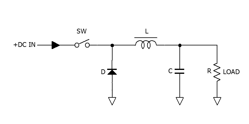 Figure 1 shows the main components: A switch (power MOSFET), a diode, an inductor, and an output filter capacitor.
When the switch closes, current starts to flow from +DC IN, through the inductor, and into the filter capacitor and load. The inductor’s magnetic field increases, storing energy; the process creates a voltage that opposes, or “bucks”, the input voltage, giving the circuit its name. During this time the diode is reverse-biased and does not conduct.
When the switch opens, the inductor opposes the change in current by reversing the polarity of its voltage drop. It releases energy by supplying current to the filter capacitor and the load through the diode, which is now forward biased.
The switch opens and closes at a constant frequency. The duty cycle (the ratio of ON to OFF time) sets the ratio of the output voltage to the input voltage. A control circuit varies the duty cycle to accommodate varying input and load conditions.
Estimating supply current requirements
The 7330’s power consumption of about 1.5 W does not change much over the input voltage range. So, to estimate the supply current, simply divide 1.5 W by the supply voltage (I = P / E). For example, the current draw from a 10 V supply is about 150 mA. From a 13.8 V supply, it’s about 109 mA, and from a 24 V supply it’s about 63 mA.
Despite these low current drain figures, don’t use small supplies such as “wall warts”; use the repeater’s supply instead. There are several good reasons:
• There are two 470-uF capacitors across the 7330’s DC power input that need to charge when power is applied, and a very small supply may not deliver sufficient startup current.
• If the site has a backup power system, you’ll want it to power the controller from the same source as the repeater.
• Most wall warts are low-quality units with short lifetimes.